The malicious macro pad
The Hak5 Rubber Ducky is a great little tool that was even featured on the TV show Mr. Robot, although, it can be rather pricy to have a whole fleet of them to perform different tasks. Dbisu on GitHub created a circuit python script that takes a Rubber Ducky payload and runs it without the need to even compile or change the format.
There are some other issues encountered with having devices that can hold 1 payload (this payload is also limited in size on the Rubber Ducky) such as when doing a physical penetration test, you may have only accounted for Windows hosts being present, or different configuration options like not needing a password to disable windows defender. This macro pad by default has 8 scripts that can be run, with a little work you could even use a full size 104 key keyboard.
Now, the general public is well aware that you should never plug in USB drives that you do not own. I would argue that the novelty of finding a ridiculously sized keyboard may even yield a higher use rate than social engineering with a Rubber Ducky but that is just speculation.
I have wanted to create a project like this for well over a year but now it is finally off the back burner and ready to go! My primary use case for this device is to store scripts for my homelab but the penetration testing ability will also be utilized by myself. I implore you to only use this tool on machines you own or have permission to do so with.
The project is far from finished, I plan to add a way to run multiple scripts in series with button presses after the device is plugged in (rather than holding a key whilst inserting the USB cable) and create a 104 key version with 2 ports, one to act as a normal keyboard and one to act as a payload injector.
Lets get on to making the macro pad!
Tools needed:
- Soldering iron
- Screwdriver
- Wire snips
- Wire stripper
- Hot glue gun
- 3d printer
- Pliers
Materials needed:
- Solder
- Wire (50 - 100cm of ~22awg)
- Hot glue stick
- 4x 4g screws
- 3d printer filament
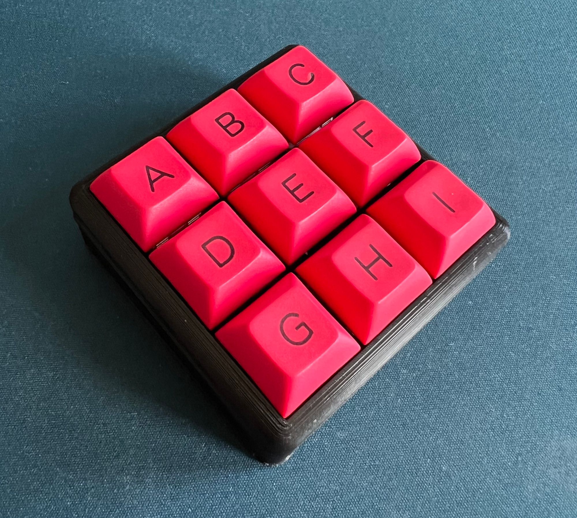
- 9x keycaps labelled A through I
- 9x keybaord switches (I used Zealios 78g but any will do)
- Optionally Kapton Tape
- USB cable
Dealing with the hardware may not be everyone's cup of tea since previous experience and specialty tools may be needed, however, it's my favourite part!
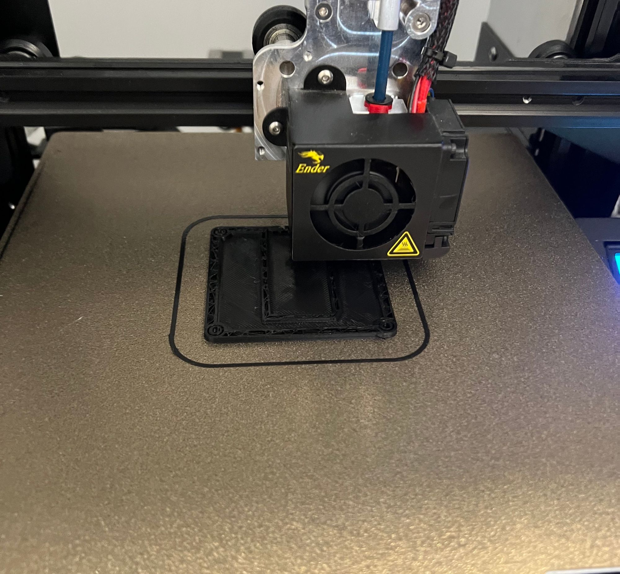
Step one: Printing the case
The STL file can be found here. It was created by user sepro over at Thingiverse and was intended for a standard USB macro pad, the write up can be found here. The settings will be different for each 3d printer and favourite slicer software. I personally used supports as my part cooling is subpar but an otherwise standard Cura profile for my Creality Ender 3. If you don't have a printer, some local libararies, maker spaces, or retail 3d printing services may be able to assist.
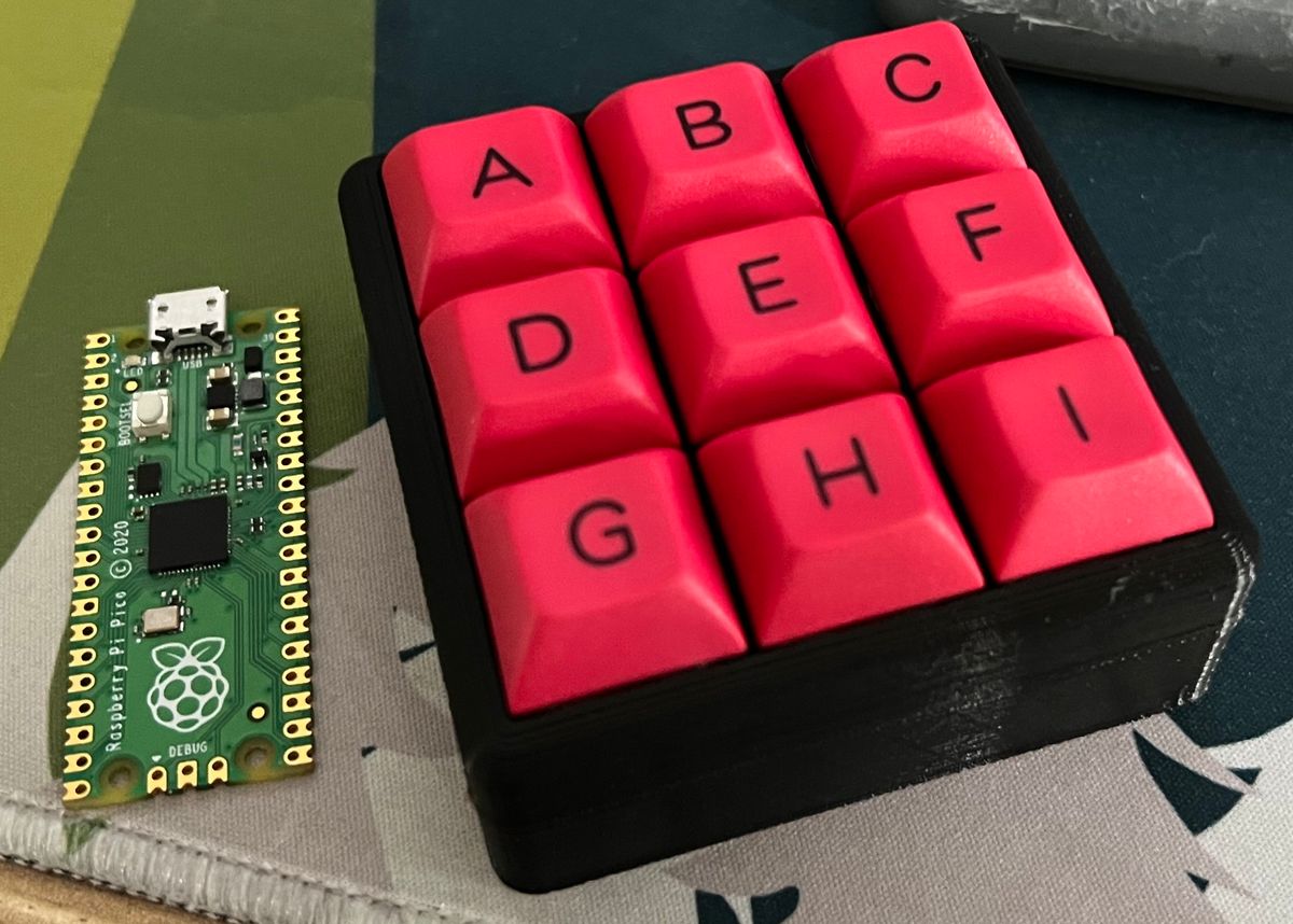
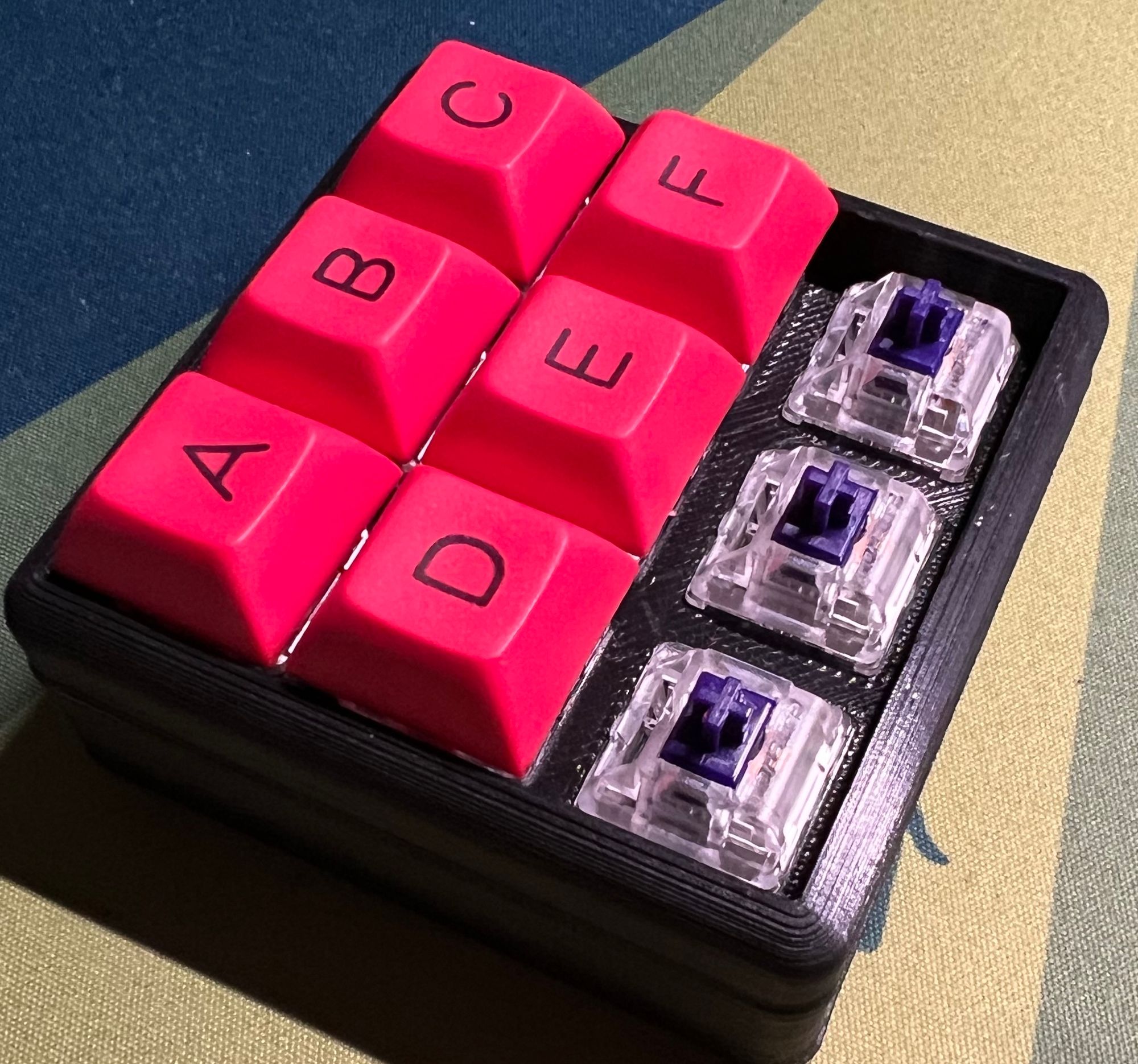
Step 2: Inserting the switches and keycaps
Insert the switches in to the top half of the case and attach the key caps. No adhesive is necessary for this step, all parts are press fit at this point.
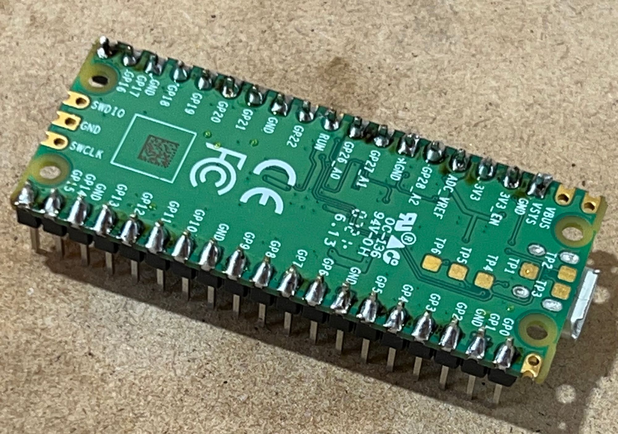
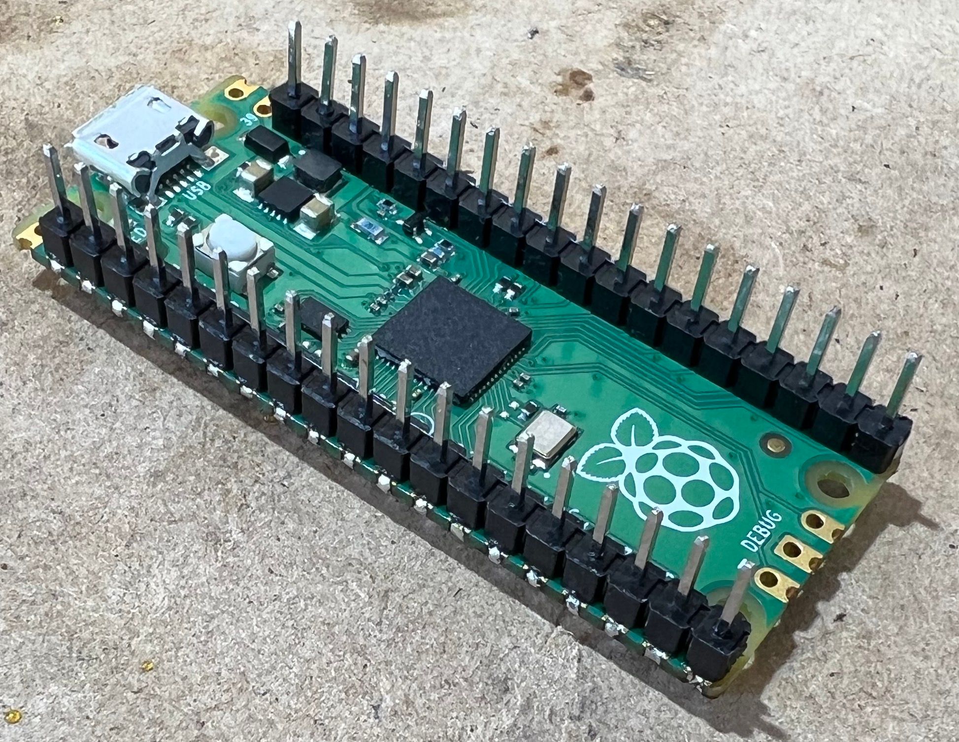
Step 3: Soldering the headers on the Pico
The case is fairly tight, it doesn't appear to have been designed to be used with headers on the Pi, snip 1 pin off each header (I originally snipped 2 off the one side before realising only 1 was necessary). The 'missing' pin will be on the micro USB end of the Pi.
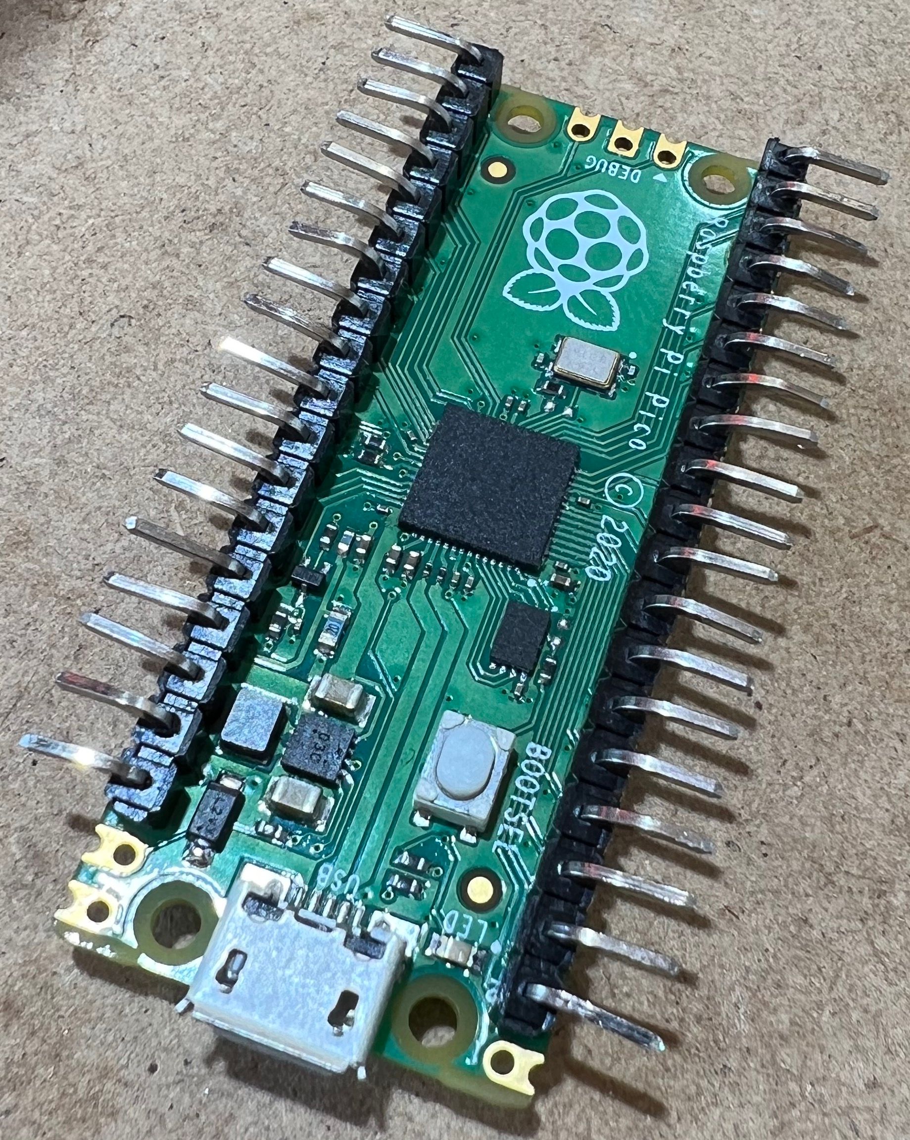
Step 4: Bending the pins to avoid clearance issues
As previously noted, the case doesn't appear to be designed for the Pico to have headers. To make some extra space, gently bend the pins outward. Please note that this can cause some damage to the board if done without caution. I used nylon tipped jewellery pliers from my local craft store. Clipping the short side of the pins also made an extra 1mm of clearance; it is not necessary but is shown in the second image below.
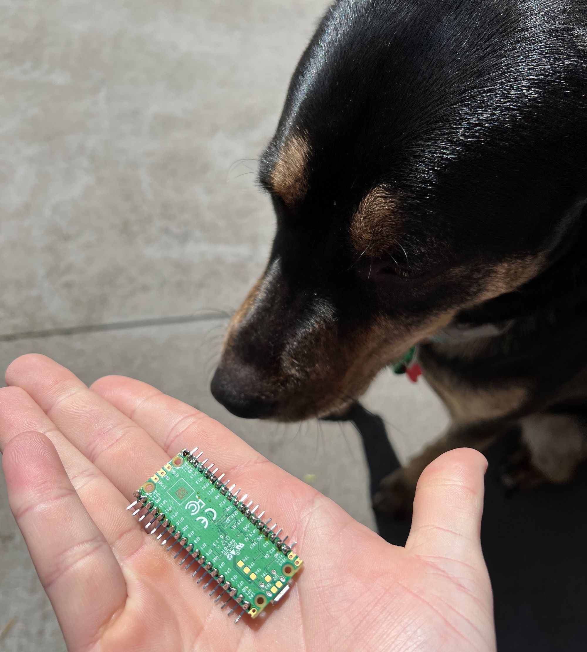
Step 4a (optional): Get the site supervisor to approve of your work so far
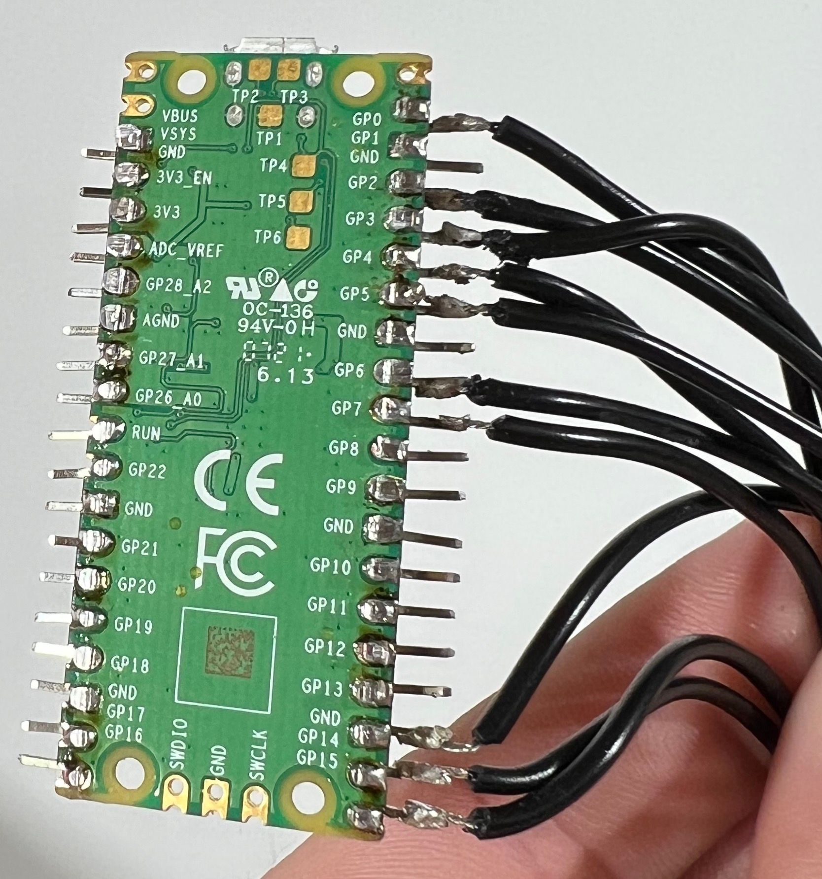
Step 5: Solder the switches to the Raspbery Pi Pico
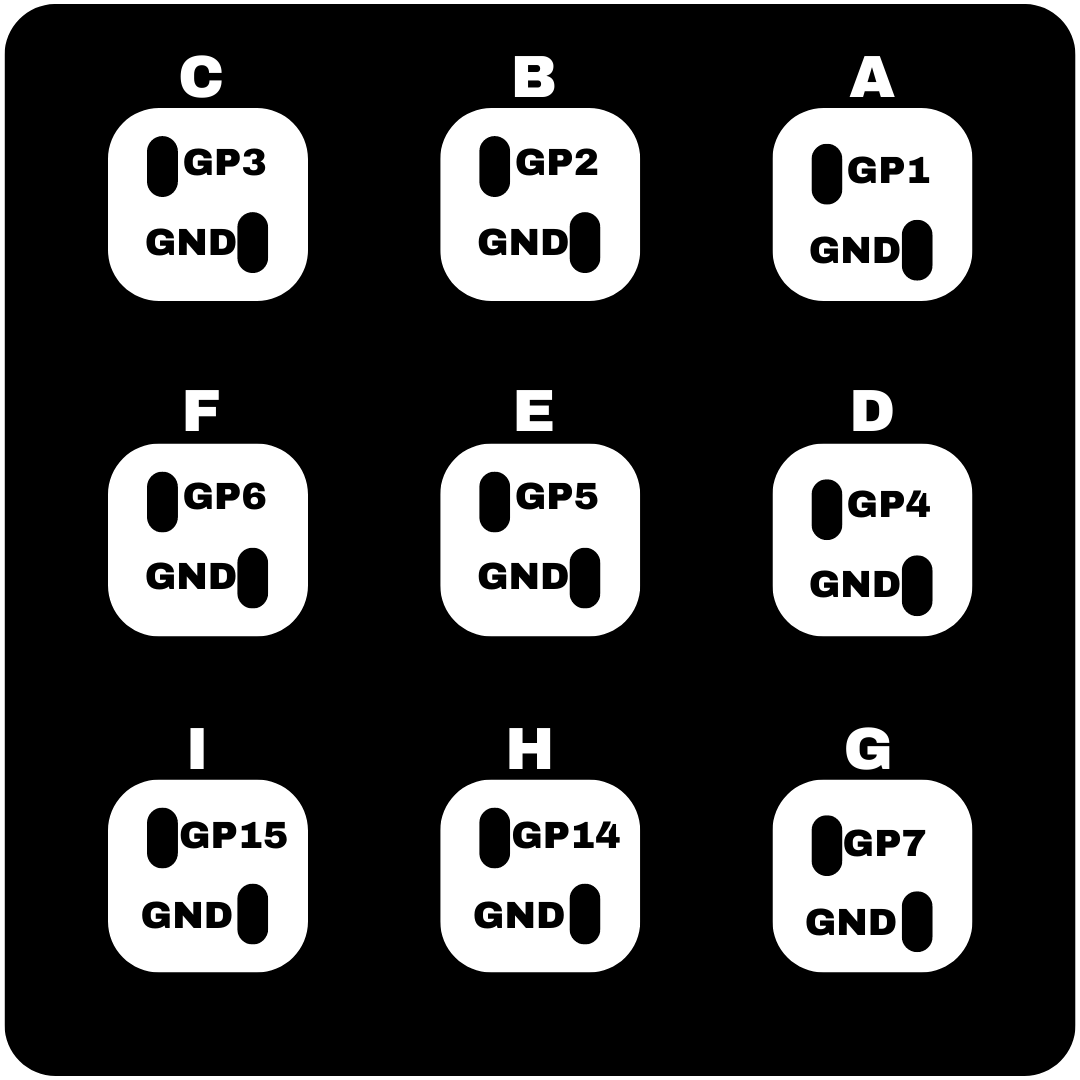
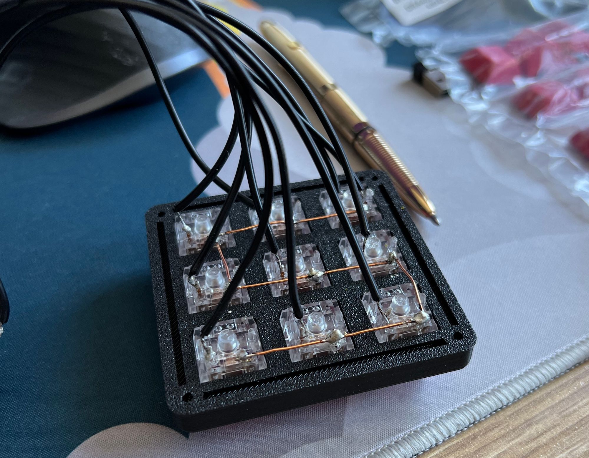
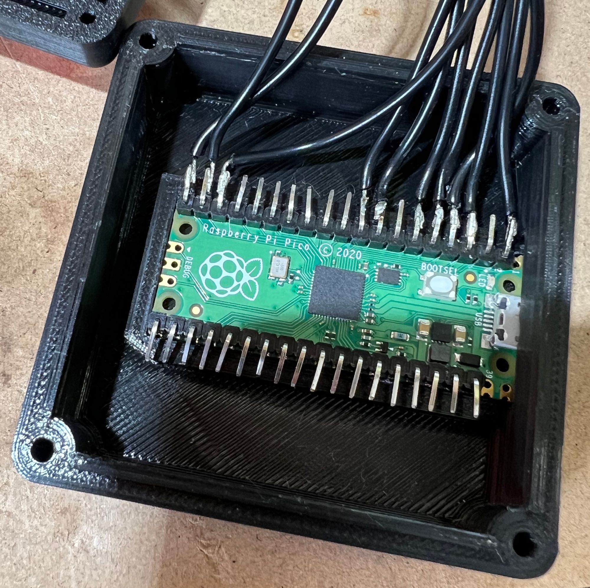
You have a couple of options here, you can connect a wire to each ground of the switches since there are several GND outputs on the Pico but I opted for a single ground wire from the pi to a solid wire ground rail that goes to each switch. Below you will find the layout for each pin of each switch in the macro pad. Please note that you are soldering from the bottom of the switch so the placement of each key is shown below to avoid confusion once flipped right side up. I used about 10cm of wire for each connection but this created a lot of excess wire, I would use 5cm if I made another one.
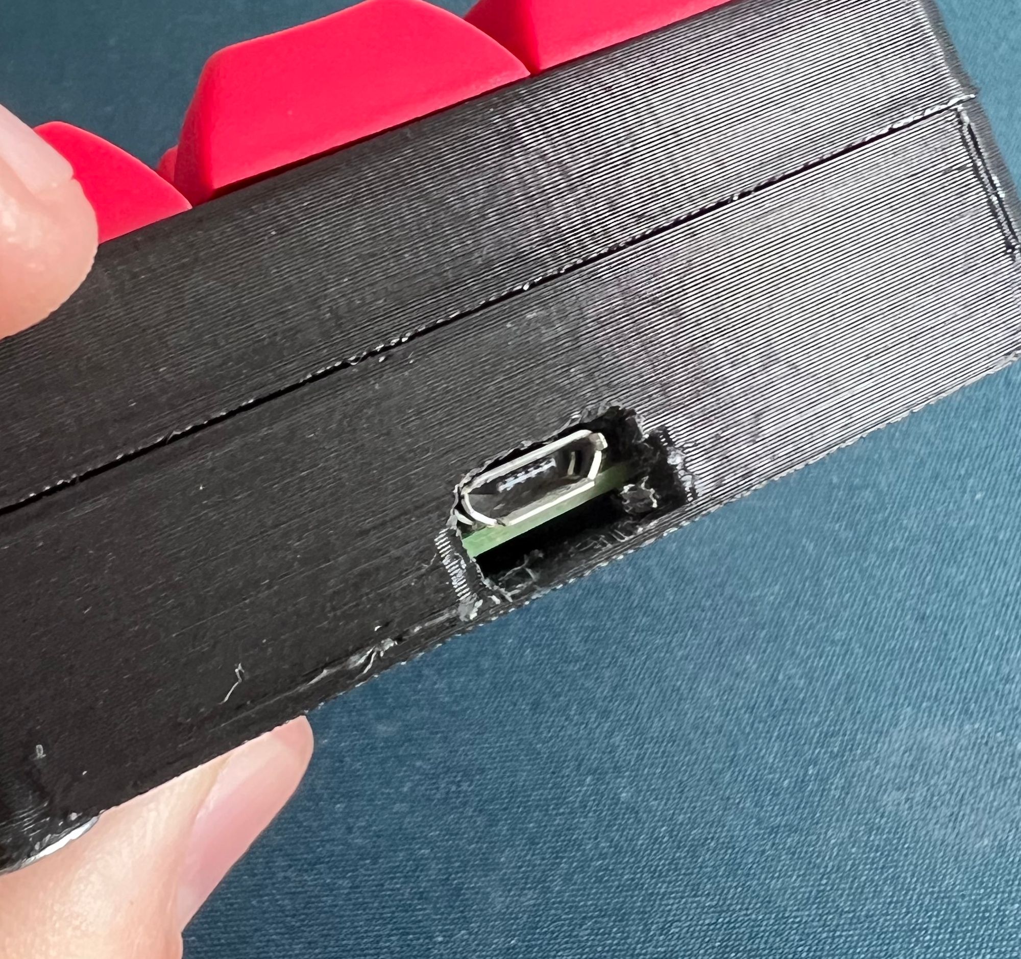
Step 6: Modifying the 3d printed case (may not be needed)
The USB port opening of my print was a little short, I removed roughly 1-2mm of plastic from the top like so:
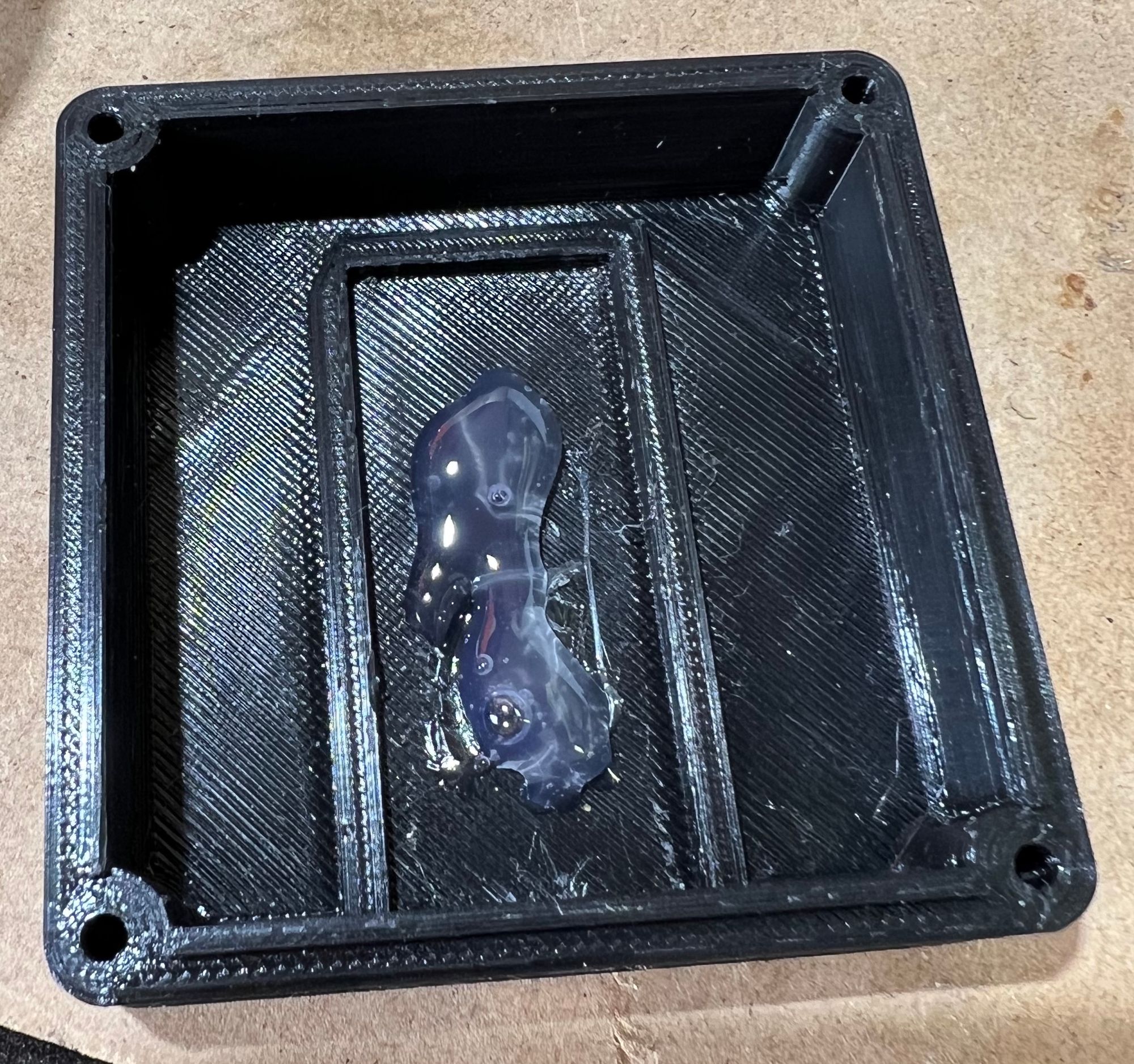
Step 7: Attaching the Pico to the case
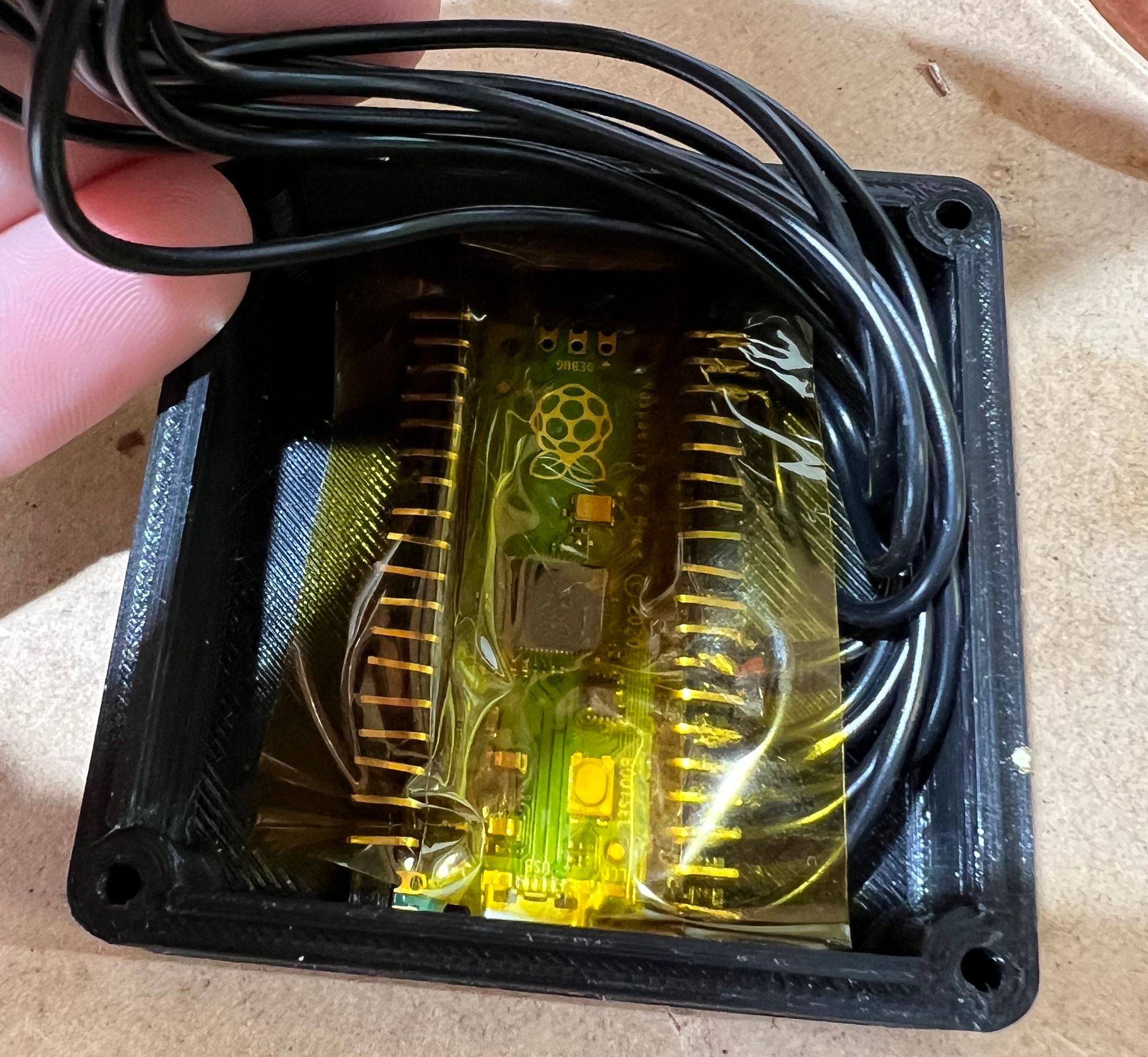
Place a small dab of hot glue in the bottom half of the case, insert the Pico and optionally a layer of kapton tape to avoid shorts in the small space.
Step 8: Sealing the case
This should wait until after the software is all loaded up in case you need access to the BOOTSELECT button on the pi to nuke the flash and start again or for initial flashing. 4x 4g screws is all that is needed, glue can be used in a pinch but is permanent.
Now it is software time! I have included test payloads for each button, these are benign and designed for a Microsoft Windows 10 hosts. Each script will open notepad and type string that explains which payload was executed.
Step 1: Plug in your Pico whilst holding down the BOOTSELECT button, you can release the button after it shows up in your storage devices as "RPI-RP2"
Step 2: Grab a copy of CircuitPython 7.x.x from here
Step 3: Copy the downloaded CurcuitPython .UF2 file on to the root of the Pico displayed as "RPI-RP2"
Step 4: Download the latest Circuit Python 7 Bundle form this repo. It will be labelled like "adafruit-circuitpython-bundle-7.x-mpy-YYYYMMDD.zip"
Step 5: Extract the zip file from step 4, navigate to the "lib" folder and copy adafruit_hid, adafruit_debouncer.mpy, asyncio, and adafruit_ticks.mpy to the "lib" folder of your Pico
Step 6: Either download the zip from this repo or clone the repo from the CLI with the command below. Place boot.py, and each one of the Payload<key>.dd on to the Pico
git clone https://github.com/yenoromm/pico-ducky-macro-pad.git
Step 7: Delete code.py from your Pico and place duckyinpython.py on your Pi. Once on the Pico, rename duckyinpython.py to code.py. Your malicious (or not) macro pad is now ready to use, unplug and get tinkering!
How to use:
If no key is pressed when plugging in the macro pad, the payload in payload.dd will be executed.
If keys A through G are pressed when inserting the USB cable to the host machine, payload<capital letter of key pressed>.dd will be used. Executing multiple payloads at once is very ill advised as they will not run properly. To use multiple payloads, do them in series one after the other.
Pressing H while inserting will show the hidden storage, by default the device only shows as a HID (Human interface device like a keyboard or mouse). Pressing I makes the device inert, it will not execute any payloads. Pressing both H and I whilst inserting the device is advised when you are configuring payloads to view the storage and not run any payloads.
All payloads designed for the Hak5 Rubber Ducky, will run on this device. A great collection of scripts can be found here. If you're feeling adventurous you can even write your own, here is the documentation. The default payloads use about 20% of the storage combined and are only the tip of the iceberg, you can run much larger and more complex payloads in production.
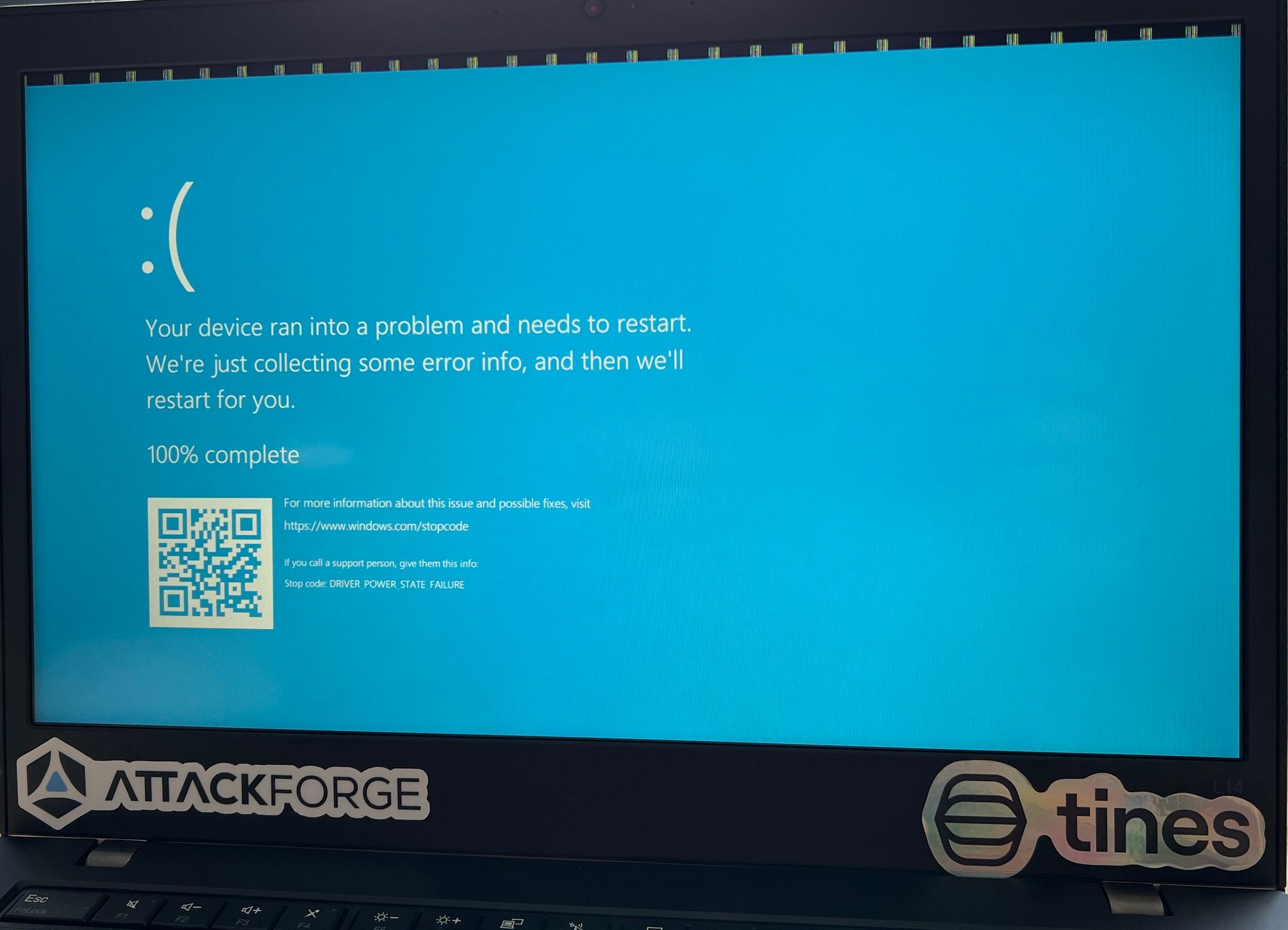
Aggressive scripts (with the macro pad or a genuine Rubber Ducky) can cause the host to BSOD or disable the USBs, make sure to test your backup strategy before targeting live machines. Let me know how you would use this device in the comments below!